Tool holders play a critical role in connecting elements and maximising machining performance. However, several different types are available and the most suitable one will depend on the operation. Consider key characteristics as they will differentiate a standard tool holder from one that’s the right choice for precise, high-speed machining. Selecting a high-speed tool holder that will consistently produce high-quality and safe operation, machine shops need to focus on balance, taper contact and accuracy. Alan Miller, Senior Engineering Manager at BIG DAISHOWA, the world-leading brand available from Industrial Tooling Corporation (ITC) discusses why these three aspects are top priorities for medical manufacturers and reveals the attainable outcomes of each.
Taper considerations
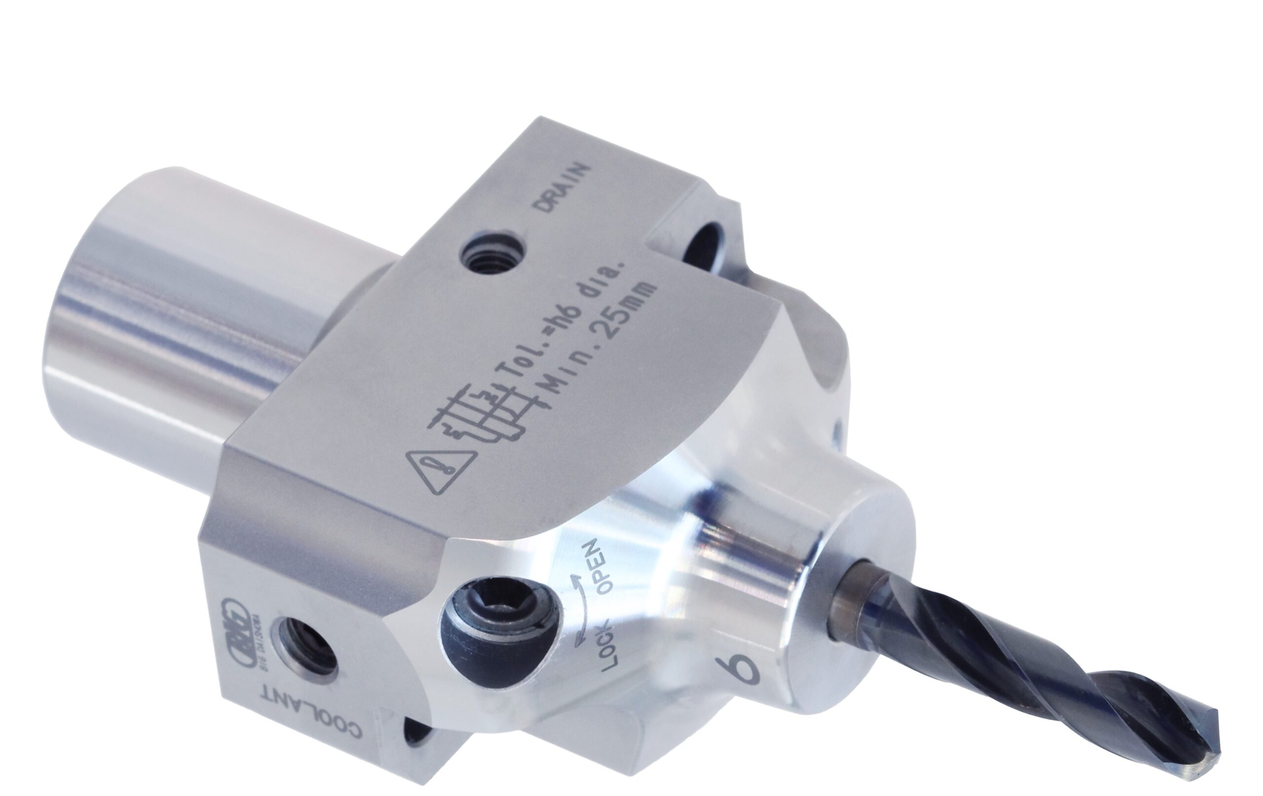
For high-precision machining, the taper must be manufactured to extremely tight tolerances for the tool holder to be accurately positioned within the spindle to provide a rigid connection for the axial and radial loads. Good repeatability in and out of the machine must maintain consistency. The requirements will depend on the tool holder type used, such as the HSK, CAT/BT, and polygon styles. HSK are hollow shank tapers available types that include A, E, and F. These offer radial stiffness and high-speed precision. This type of taper is much shorter (25mm, 32, 40, 50, 63, 80, 100, and 125mm) and includes an internal mechanism for radial and axial connection.
“Since this is a hollow taper and is small, material selection is extremely important,” Miller says. “HSK is clamped by fingers reaching inside that hollow core and pulling and stretching the taper back into the spindle. The wall thickness is very thin, and it’s critical to have a very high-quality grade of steel, which is why we use die steel for the very small tapers.”
Another important consideration for HSK types is the finishing of clamping features after heat treatment because the fingers reach inside and grab on a feature inside the hollow taper, so making sure it’s finished after heat treatment assures it’s in the correct location to provide more accurate repeatability in the spindle.
CAT and BT style are steep taper tool holders with a more traditional style cone. Both have a 7:24 taper ratio and require a retention knob or pull stud to secure the holder within the machine spindle. As the machine grabs and pulls, the spindle expands to secure taper contact. With the larger size and the cone shape of the spindle, the taper will open as speeds increase significantly. As the spindle opens, the force of the clamping unit draws the holder deeper into the spindle, which causes the tool holder to lose some accuracy.
To address this issue, BIG KAISER’s BIG-PLUS spindle system available from ITC allows the shank to contact the spindle taper and the spindle face simultaneously, allowing increased tool rigidity due to the larger contact diameter of the tool holder flange face. Larger face contact, combined with the taper contact, works together to resist deflection.
The Polygon taper types put the face and taper of a machine spindle and tool holder in contact, ensuring high repeatability. The polygon design also allows for self-centring to improve accuracy. However, these types are more difficult to grind because of the slope, so it takes a high-end machine to achieve the desired accuracy.
Tool holder balance
As spindle speeds increase, it becomes more important to obtain tool holder balance. Balanced tool holders allow users to run at the highest spindle speeds and feed rates while maximising tool life, surface finish and spindle life. Balancing ensures the cutting edge of the end mill consistently engages with the material to prevent chatter and poor surface finish quality.
“For balance, we’re talking about side loads generated by that unbalanced mass running at high speeds,” Miller explains. “So, that can influence the bearings of the machine tool spindle to the actual cutting performance on the business end of the cutting tool. It’s very important to consider, and there’s a new ISO toolholder balance standard that was released in 2017 to further help users meet requirements.”
The updated ISO 16084 standard accounts for all variables for safe and productive machining. Miller says it also takes into consideration additional, more complex factors that can lead to imbalance. It focuses on the interaction between the spindle and tool by factoring in the allowable load on the spindle bearings generated by the tool’s imbalance.
The best way to ensure balance is to measure the tool holder as a full assembly. Ultimately, this will result in a better-performing tool. Although each part can be balanced individually, this will not guarantee the highest level of overall balance.
The benefits of balancing include optimal surface finish, machine sustainability, better part geometry and extended spindle life.
Miller also cautions: “When dealing with balance, there’s also a point that we can get to a plateau, where additional balancing won’t help anymore. The goal could be exact balancing, but we’re going to spend a lot of time on every tool, trying to achieve that same amount of balance, and it becomes more or less stable. No matter how much more balancing you do, it won’t change the way the tool performs.”
Accuracy
Improved quality will depend on the accuracy of the tool, which is largely affected by tool runout. Very low runout of the tool holder will give users better quality and improved cutting for more consistency and lower costs.
“Runout accuracy is a very important consideration. Low runout will give you better part quality and it will improve cutting tool life and allow you to get more consistency, longer run times, and fewer tool breakages,” Miller adds.
BIG DAISHOWA designs and machine tool holders to reduce runout, by using precision materials, production processes and heat treatment selected for precision. This includes pull studs built with through-hardened H13 premium tool steel, all features are precision ground. Each collet is inspected for 100% concentricity, guaranteeing runout within 0.001mm at the nose. Most of the general customer base, as Miller has found, follows the guidelines of 0.007mm to 0.0013mm to be a good runout. However, this may only give about 50% to 60% of the potential cutting tool lifespan.
“Our programs are down to 0.0002mm and 4x diameter to make sure you have accurate tool assemblies,” Miller says. “All of our collet chucks and finishing tool holders guarantee that runout accuracy is about 3 to 5 times better than what is considered good.” Runout can also impact cutting force, which can cause vibration and ultimately inhibit machining accuracy. “Vibration is challenging the function of the cutting parameters, mostly back to the cutting speed and rotational speed,” Miller explains. “The best tip that we have for anyone experiencing vibration is to adjust the speed in one direction or the other, change lanes and get into a harmonic situation.”
Cooling systems
There are future developments that BIG DAISHOWA has developed, such as tool holders for CO2 cooling systems to eliminate liquid coolant for metal cutting. They reduce the amount of contamination that medical parts have within the machining process but still cool the cutting tools so users get a good tool life. These capabilities are built into Mega micro chucks, featuring a slim nut and taper design to prevent interference in applications with micro drills and end mills. The notch-free nut prevents vibration and noise and offers superior balance and concentricity.
“The jet coolant nut was designed around those types of developments where we can offer unique components specifically for carbon dioxide cooling style machining that’s becoming more important to the medical community,” Miller concludes.