Electrified mobility – Reliable machining of small housings for electric motors made of magnesium and aluminium
In 2019, on average every third bicycle sold in Germany was an e-bike – a total of 1.36 million units. According to Zweirad-Industrie-Verband, this brought the total in Germany to 5.4 million.
The production of e-bikes
In Germany alone, manufacturers produced one million electrically powered bicycles in 2019. The motor housings, among other things, pose a challenge during the production phase. After all, they have to be small and light and at the same time highly accurate. The small size of the entire drive is a result of the limited space available on an e-bike. Most of the motors are installed directly in or onto the frame itself as unobtrusively as possible. The entire drives must be particularly light-weight to ensure a long battery life. The less loads have to be moved, the less the motor has to “work” and the longer the battery can go without needing to be charged. After all, the housings must be manufactured with high precision to ensure that the motor runs both quietly and smoothly. As well as this, only a precisely manufactured motor runs smoothly and achieves the highest possible level of efficiency.
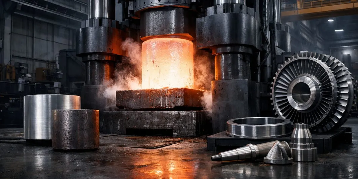
As a result of the requirements mentioned above, most manufacturers of small electric motors produce their motor housings from die-cast aluminium, more often from die-cast magnesium. Both workpiece materials are low in weight. Magnesium has a density of 1.7 g/cm3 and so is slightly lighter than aluminium with a density of 2.7 g/cm3. On top of this, magnesium is even easier to cast than aluminium. This allows for designs with even thinner walls and more intricate structures. Whether they’re made from aluminium or magnesium – most motor housings consist of the actual housing plus one or two covers. They have very thin walls and are unstable, so are therefore susceptible to vibrations. Multi-stage contours within the housing provide space for the various functional components of the motors. The geometric and dimensional requirements are high – narrow shape, running and position tolerances are specified.
The motor housing challenge
“For machining the housings, the properties of the material and the thin walls of the part pose the greatest challenges”, says Leander Bolz, Sales Manager at the MAPAL Centre of Competence for PCD tools. Furthermore, the housings are often already coated when they are machined. These coatings must not be damaged during machining. “Our customers in this sector produce very high volumes, so it is equally important that the tools for machining are highly economical to use”, adds Bolz.
Over the past decades, MAPAL has gained extensive experience in the machining of small motor housings in both aluminium and magnesium. “Small housings have always been used for chainsaws, mopeds or lawnmowers, for example, but with electrification the precision requirements have increased even more”, explains Leander Bolz. And so MAPAL has adapted its programme for the complete machining of small housings to the changed conditions. First and foremost, PCD and solid carbide tools are best suited for machining both workpiece materials. In some cases, the tool experts design the process as dry machining. Polished chip spaces and particularly smooth surfaces on the tools stop them from getting dirty. They make the machining process safe even without the need for a cooling lubricant.
“When it comes to designing the tools for machining a magnesium housing, we’re always at the upper tolerance limit in the first step”, explains Bolz. This is because stresses inside the workpiece, different coating thicknesses or the ductility of the material, which contracts after machining due to the heat introduction, cause deviations in some diameters and bearings. “It’s only after a test drilling with a subsequent dimensional check on the part that we determine the required tool diameters, which also apply to the subsequent tools”.
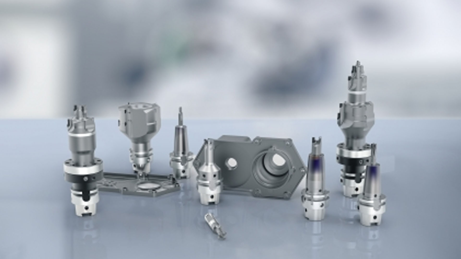
Most economical solution thanks to combination tools
In order to make the machining of motor housings as economical as possible and keep non-productive time to a minimum, several work steps are combined for the individual tools.
PCD tool machines bearing and position bores
One example is the tool for machining the bearing seat of a magnesium housing. “During this machining process, we had to deal with strong vibrations as the part has extremely thin walls, especially in the area of the third bearing bore”, recalls Leander Bolz. The tool must remove 0.6 – 1 mm of material at the pre-cast bores.
The customer had high demands:
Roundness < 0.01 mm
Diameter tolerance IT7
Average roughness depth Rz < 10 µm
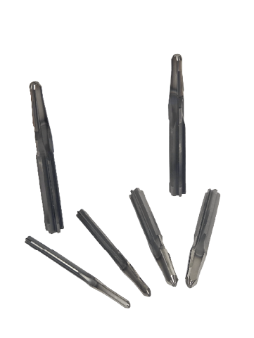
MAPAL designed a complex, multi-stage PCD combination tool for this. “This allowed us to machine the three bearing bores and the position bore of the bearing seat in one go – in a way that was process reliable and within the required tolerances”, says Bolz.
The tool works with the following cutting values:
Spindle speed 8,000 rpm
Feed rate 3,200 – 4,800 mm/min
Feed 0.1 – 0.15 mm
Drilling and milling combined in a single tool
Another tool combines milling and drilling processes. While drilling steps machine the bearing bore and position bore, a milling step is used to produce the sealing slot. “With this tool too, our main task was to prevent vibrations and reduce the cutting pressure”, explains Bolz. The tool experts achieved this by optimally coordinating the number of teeth and geometry of the milling step. “This also helps us avoid chips in the slot and ensures that the milling process runs reliably”, says Bolz.
The milling step for the tool works with the following cutting values:
Spindle speed 8000 rpm
Feed rate 7,200 mm/min
Feed 0.15 mm
MAPAL offers the complete package
MAPAL also designed the other tools for the complete machining of the housing as combination tools. “For one of our customers, we process the complete housing with only eight different tools”, says Bolz. However, this number varies depending on the part, workpiece material and requirements. Another customer with a much more complex housing requires 31 tools. “Today we offer the complete package for the machining of small aluminium or magnesium housings. Depending on requirements and complexity, we design the appropriate tool concept”, concludes Bolz.