
The history of machining involves constantly evolving technology, with machines, cutting tools and components advancing at different paces and often leapfrogging one another. As spindle speeds began to increase in early 1990s, a group of international manufacturers, academics and the Association of German Tool Manufacturing came together to make sure toolholder performance didn’t fall behind. Their work produced the German DIN standards for HSK toolholders and spindles.
Here’s the fun part: there’s not just one style of HSK toolholder. The group defined a total of six (!) HSK styles, represented with the letters A through F. Each style features different characteristics for targeted applications, but in a nutshell: styles A, B, C and D were designed for standard applications, and styles E and F were designed for higher speed applications.
In this article, you’ll find a quick primer on HSK, as well as deeper dives into the three most popular HSK forms: A, E and F.
The Basics of HSK
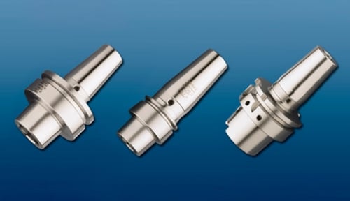
The defining characteristic of HSK toolholders are their hollow 1/10 taper. During high-speed rotation, spindles can tend to bellmouth slightly, sucking a traditional steep taper toolholder (CT, BT, NMTB) into the spindle and negatively impacting machine precision. The hollow taper of HSK toolholders are designed to expand with the spindle, with the elastic deformation of the taper ensuring consistent and solid contact with the spindle wall.
Additionally, when an HSK drawbar clamps the toolholder, the toolholder is drawn into the spindle, making a second contact surface between the toolholder flange and spindle face. This helps ensure positioning accuracy, and provides additional support against radial forces during heavier cutting.
HSK toolholders come in a range of sizes directly related to the flange diameter in millimeters: 25, 32, 40, 50, 63, 80, 100, 125 and 160.