As an independent research and technology organisation, TWI Ltd has recently invented a highly disruptive, new sub-surface machining technique called CoreFlow™. As soon as MTD magazine heard the term ‘Sub-Surface Machining’, we were intrigued, so here Senior Project Leader, Vito Di Pietro takes us through this ground-breaking innovation.

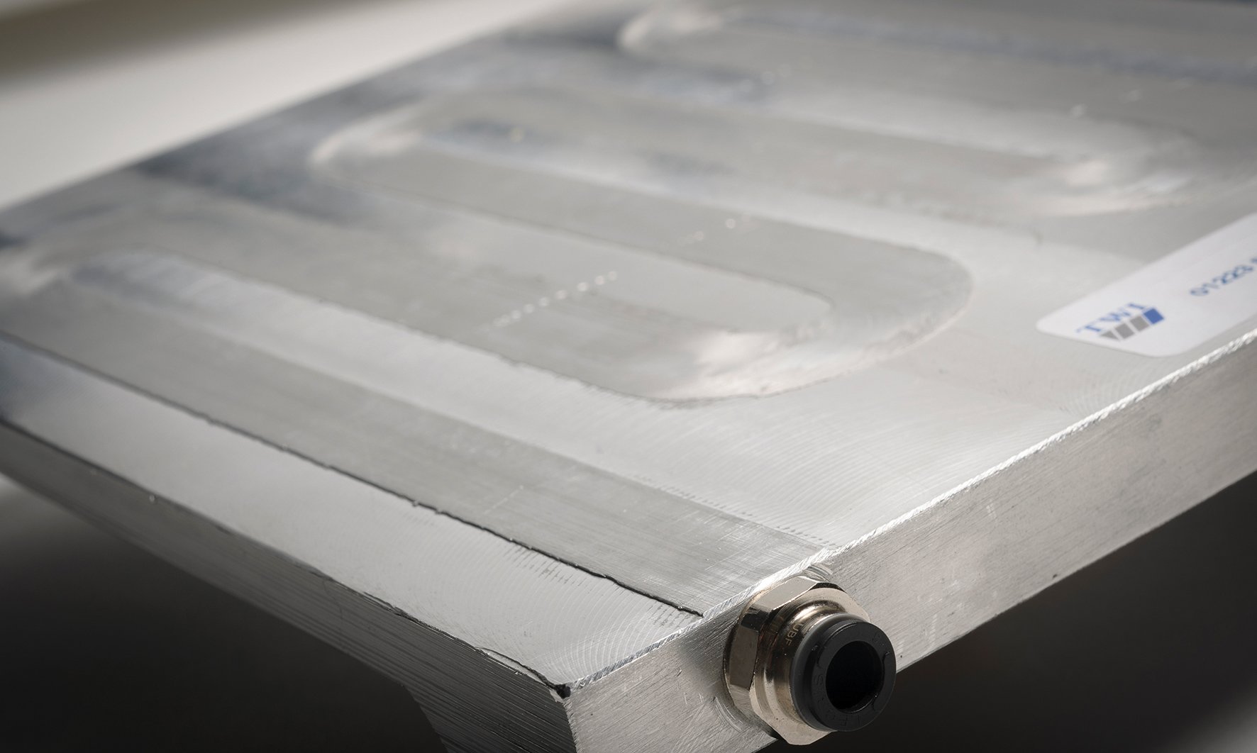
This new solid-state process is an evolution from friction stir welding (FSW) and friction stir channelling (FSC) that allows for sub-surface networks of channels to be machined into two-dimensional or three-dimensional monolithic parts in a single manufacturing step. These channels can then be used for applications such as heat exchange. Figure 1 shows a cooling plate demonstrator recently produced in aluminium (AA6082-T6) with infrared thermal imaging evidencing the circulation of liquid coolant.
At the forefront of solid-phase friction welding and processing technology, TWI has been innovating welding research and development since the 1960s, responding to industry needs and providing consultancy and support to all industry sectors. Providing everything from advice on component design, process selection and quality issues, troubleshooting, feasibility and pre-production trials, application, and prototype equipment development, TWI has been responsible for many key innovations and developments in solid-phase joining. The most notable examples are friction stir welding (FSW), invented at TWI in 1991, and the development of linear friction welding (LFW) into a mature joining process for turbine blades.
The uptake of FSW has been very rapid, especially when compared with other innovations in materials joining. First demonstrated in the laboratory in late 1991, by 1995 it was in industrial production fabricating panels for refrigeration purposes. Many other applications rapidly followed including its use in launch vehicles, railcars, airframes, automotive structures, heat sinks and ships.
FSW uses a rotating tool designed to generate frictional heating to soften the adjoining metal to a point where it can be viscoplastically deformed and displaced around the tool (Figure 2). The FSW tool traverses the joint line between two parts, where its stirring action enables the formation of a solid-state weld. This has revolutionised welding of aluminium alloys due to the sub-melting point processing conditions, which prevent solidification cracking and porosity formation while reducing distortion and minimising the loss of parent material properties. The resulting joint has excellent tensile strength and fatigue and fracture properties.
 Derived from FSW, Friction Stir Channelling (FSC) is an innovative solid-state process that integrates sub-surface networks within metal structural elements. The original FSC concept was patented by Rajiv S. Mishra in 2005. In his work, poor material consolidation during FSW was deliberately promoted to produce a continuous void along the tool path. However, despite its great potential, this technology has not yet been adopted by industry, mainly by not fulfilling the required repeatability, surface finish or design flexibility.
TWI has recently invented and patented a new stationary shoulder variant of FSC (SSFSC) which has overcome many drawbacks of conventional FSC. As shown in Figure 3, a stationary shoulder is employed to confine the nugget of viscoplastic material, limiting the flow of material extracted by the probe. With the appropriate rotation direction, the geometrical features of the probe causes part of the nugget material to be conveyed into the shoulder. The material extracted is then re-directed towards a series of vents in the shoulder and expelled.
As the tool assembly traverses along a pre-defined path, the process of extracting the material leads to the formation of a closed channel within the workpiece and the production of extruded wire.
The four main stages in the process are shown in Figure 4. The cycle is initiated by plunging the rotating probe into the plate and once the probe reaches its target plunge depth, the machine initiates its traverse motion along the workpiece, the plasticised material is conveyed upwards by the rotating probe threads, into the shoulder and then expelled as extruded material. This subtraction of material leads to the formation of a closed sub-surface channel.

Applications for CoreFlow™
CoreFlow™ already looks set to find revolutionary applications in the manufacture of heat exchangers, cooling systems, integrated fluid management and the light-weighting of structures. Heat exchangers can be found everywhere from cars to aeroplanes, but also communication platforms, satellites and ships.
The automotive opportunities
In the electric vehicle (EV) market, there is an increasing need for faster-charging rates, improved speed and autonomy, increased power density, and a general ambition to make EVs affordable. These expectations are resulting in increased heat generation and are driving a collective demand for low cost, compact, lightweight and efficient heat transfer solutions.
 Battery packs release heat during charging and driving due to electric resistivity. This is aggravated for higher intensity charges and discharges. Currently, serpentine pipe heat exchangers are incorporated inside the battery pack to prevent excessive temperatures that could lead to cell chemical degradation or battery derating. These systems take up space, add weight and manufacturing complexity to the vehicle, therefore CoreFlow represents a huge opportunity to solve these challenges by manufacturing battery trays with integral cooling channels built into the metallic structure.
Another example is the thermal management of electric motors. These components heat-up mainly due to the resistivity of the copper windings and eddy-current losses, this excess heat is detrimental to motor performance. Cooling systems are usually incorporated into the casing based on natural or forced convection of air or liquid. CoreFlow™ could be used to incorporate channels in thin-walled motor casings for active cooling, reducing weight and improving performance.
 The aerospace industry is another potential beneficiary. Aircraft engine cooling is usually performed by heat exchangers located between the engine and the nacelle, cooling engine oil using air or fuel. These components disrupt airflow, create drag and decreasing thrust. With CoreFlow™, cooling networks could be incorporated directly in the nacelles. The same applies to hydraulic cooling systems that could be replaced by integrated CoreFlow™ manifolds rather than hoses and pipes.
Currently, FSW is one of the most promising technologies for manufacturing heat exchangers. Their complex geometry currently forces engineers to split production in two stages (see Figure 5). Typically, a housing is machined from a solid block of metal that incorporates cooling features and channels to circulate the cooling fluid through the part. In the second stage, a lid is joined and friction welded to isolate the cooling channels from the environment. FSW has become the most effective solution for this process.
CoreFlow™ has overcome these challenges by machining the cooling channels in a single step. By creating a channel below the surface of a structure, CoreFlow™ provides an integrated method to vent heat from a part without having to add pipework or other complex and costly solutions.
This creates a simpler, more efficient manufacturing method, using approximately 20% less raw material, producing almost 80% less waste (in form of wire), and weighing less than its conventional counterpart (see Figure 5).
This new technique provides heat reduction and can be used for the production of anti-icing features on wings and flight control surfaces for aircraft. The technique can also be used to create lubrication networks for hydraulics, to embed instruments into a structure, to perform cable management or simply for light-weighting. Outside of transport, CoreFlow™ can be used for cooling data servers, communication infrastructures and radar installations or to manage the thermal load in manufacturing equipment – opportunities are huge.

Aluminium AA6082-T6 and AA1050-H14 plates with a thickness from 5 to 50mm have been successfully processed and the application has already moved on to flat and tubular demonstrators (see Figure 6 below) that feature channels along linear and helical trajectories. The demonstrators passed both leak and pressure testing, with leak rates well below 10-8 mbar∙L/s and pressure up to 9 bar.
 The development of CoreFlow™
In the last few years, CoreFlow™ has been demonstrated and further developed by TWI. Trials have been conducted on an ESAB SuperStir™ machine (Figure 7) with a purpose-built FSW gantry fitted with TWI’s proprietary stationary shoulder system.
The probe used is a cylindrical proprietary cobalt-nickel-chromium alloy threaded probe with a diameter of 9.8mm and a length of 7mm. The shoulder has a flat surface, a 30mm outer diameter and a bore diameter of 10mm. The shoulder features four orthogonally-positioned, radial vents with 3mm diameter holes that increase to 5mm to ease the expulsion of plasticised material. The probe and shoulder are usually designed specifically for the material and application.
 In Figure 8, an aluminium AA6082-T6 test piece with a thickness of 15mm has been processed with CoreFlow™ using two main process parameters; traverse and rotation speed.
In Figure 9, the superficial appearance of samples produced using rotational speeds varying from 400 to 1200rev/min and traverse speeds from 25 to 150min/min are shown. Fully-consolidated ceilings are achieved when combining low traverse speeds with low rotation speeds whilst increasing the rotation speed resulted in intermittent surface voiding; an effect more noticeable for higher traverse speeds tested.
 All channels feature a flat bottom surface with well-defined edges, coincident with the probe outline (Figure 10). The channel produced is fully consolidated and is 9.89mm wide with a maximum height of 2.53mm and a minimum ceiling thickness of 4.46mm. From the micrograph, it is also possible to appreciate how the anisotropic grain orientation in the parent material, caused by the plate sample rolling process, transforms into a fully recrystallized microstructure in the channel ceiling due to the stirring action of the probe.
The material extruded in the form of wire can be used as feedstock for processes such as wire-based additive manufacturing or even welding wire. CoreFlow™ is capable of extruding an unlimited length of wire from a plate or a pipe.
This process, labelled ForgeWire, is of great interest for producing a spool of wire from materials with poor extrudability, such as alloys of aluminium or magnesium. Wire manufacturers or additive manufacturing process developers now have a quick option for producing wire with tailored chemical composition and from experimental alloy formulations (e.g. Aluminium-Lithium or Aluminium-Scandium), potentially even directly from the rolled product or cast billets.
 TWI is continuing to develop CoreFlow™ by defining guidelines for use with different materials while working on a range of industrially-relevant demonstrators. With a variety of applications having already been proposed, this new friction technique is potentially the next paradigm shift forward in manufacturing technology.
0:00 / 0:00